1. 서킷에서 사용하는 아두이노 보드는 아두이노 우노(UNO)이다.
2. 디지털 신호
: 신호를 주는 시간의 흐름이 불연속적
** 아두이노에서 디지털 신호 핀
: 입력과 출력 모두 가능,
총 14개의 디지털 핀(0 ~ 13번)이 있다.

3. 아날로그 신호
: 신호를 주는 시간의 흐름이 연속적
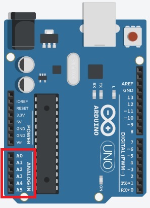
** 아두이노의 아날로그 입력 핀
: 항상 입력을 위해 사용되는 핀,
총 6개의 아날로그 핀(A0 ~ A5)이 있다,
디지털 핀에서 사용했던 pinMode() 함수를 사용할 필요가 없다.
4. 가변저항(potentiometer)
: 전자회로에서 저항값을 임의로 바꿀 수 있는 저항기이다.
5. 07_01 가변저항

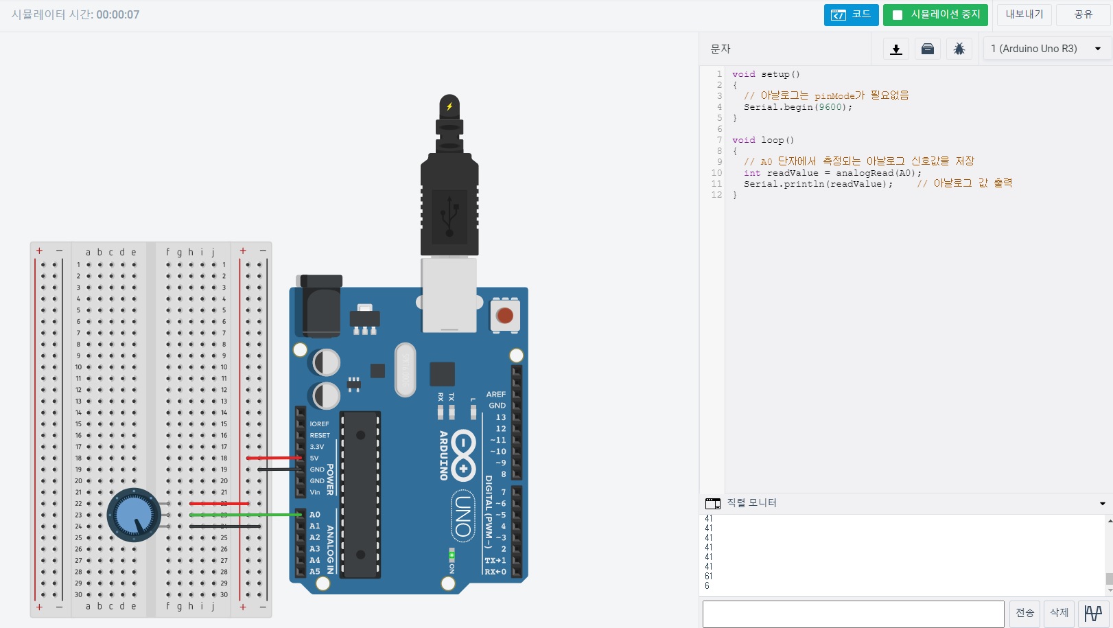
void setup()
{
  // 아날로그는 pinMode가 필요없음
  Serial.begin(9600);	// 시리얼 통신 초기화
}

void loop()
{
  // A0 단자에서 측정되는 아날로그 신호값을 저장
  int readValue = analogRead(A0);
  Serial.println(readValue);	// 아날로그 값 출력
}
6. 07_02 가변저항 LED
** 저항 : 220Ω


void setup()
{
  // 아날로그는 pinMode가 필요없음
  Serial.begin(9600);	// 시리얼 통신 초기화

  pinMode(13, OUTPUT);	// 디지털 13번 핀 출력모드로 설정
}

void loop()
{
  // A0 단자에서 측정되는 아날로그 신호값을 저장
  int readValue = analogRead(A0);
  Serial.println(readValue);	// 아날로그 값 출력

  if(readValue < 500) {
  	digitalWrite(13, LOW);	// LED 꺼짐
  } else {
  	digitalWrite(13, HIGH);	// LED 켜짐
  }
}
7. 07_03 가변저항 LED깜빡임
** 저항 : 220Ω


void setup()
{
  // 아날로그는 pinMode가 필요없음
  Serial.begin(9600);	// 시리얼 통신 초기화

  pinMode(13, OUTPUT);	// 디지털 13번 핀 출력모드로 설정
}

void loop()
{
  // A0 단자에서 측정되는 아날로그 신호값을 저장
  // 0 ~ 1023
  int input = analogRead(A0);
  int output = (float)input / 1023 * 2000;

  Serial.print(input);	// 아날로그 값 출력
  Serial.print("\t");
  Serial.println(output);

  digitalWrite(13, LOW);	// LED 꺼짐
  delay(output);	// ms 단위
  digitalWrite(13, HIGH);	// LED 켜짐
  delay(output);
}
8. 디지털 핀 : 물결모양이 아날로그 출력 가능
9. 07_04 아날로그 LED막대
** 저항 : 220Ω


const int led[6] = {3, 5, 6, 9, 10, 11};
const int analogPin = A0;

void setup(){

}

void loop()
{
	int sensorInput = analogRead(analogPin);

	/*
	// 3번 핀 LED (led[0])
	// 가변저항 값이
	// 0 ~ 171 사이에선 서서히 밝아지고
	// 171 이상이면 완전히 켜진 상태.
	if(sensorInput/171 >= 1 + 0) {
		analogWrite(led[0], 255);
	} else if (sensorInput / 171 >= 0 + 0) {
		analogWrite(led[0], int(sensorInput % 171 / 171.0 * 255));
	}

	// 5번 핀 LED (led[1])
	// 가변저항 값이
	// 171 * 2 사이에선 서서히 밝아지고
	// 171 * 2 이상이면 완전히 켜진 상태.
	if(sensorInput/171 >= 1 + 1)  // 171 * 2 상태
		analogWrite(led[1], 255);
	else if (sensorInput / 171 >= 0 + 1)  // 171 * 1 상태
		analogWrite(led[1], int(sensorInput % 171 / 171.0 * 255));


	if(sensorInput/171 >= 1 + 2)  // 171 * 3 상태
		analogWrite(led[2], 255);
	else if (sensorInput / 171 >= 0 + 2)  // 171 * 2 상태
		analogWrite(led[2], int(sensorInput % 171 / 171.0 * 255));

	if(sensorInput/171 >= 1 + 3)  // 171 * 4 상태
		analogWrite(led[3], 255);
	else if (sensorInput / 171 >= 0 + 3)  // 171 * 3 상태
		analogWrite(led[3], int(sensorInput % 171 / 171.0 * 255));


	if(sensorInput/171 >= 1 + 4)  // 171 * 5 상태
		analogWrite(led[4], 255);
	else if (sensorInput / 171 >= 0 + 4)  // 171 * 4 상태
		analogWrite(led[4], int(sensorInput % 171 / 171.0 * 255));

	if(sensorInput/171 >= 1 + 5)  // 171 * 6 상태
		analogWrite(led[5], 255);
	else if (sensorInput / 171 >= 0 + 5)  // 171 * 5 상태
		analogWrite(led[5], int(sensorInput % 171 / 171.0 * 255));
	*/


  for(int n = 0; n < 6; n++) {
  if(sensorInput/171 >= 1 + n)  // 171 * 6 상태
		analogWrite(led[n], 255);
	else if (sensorInput / 171 >= 0 + n)  // 171 * 5 상태
		analogWrite(led[n], int(sensorInput % 171 / 171.0 * 255));
  }

}
10. 조도센서(photoresistor)
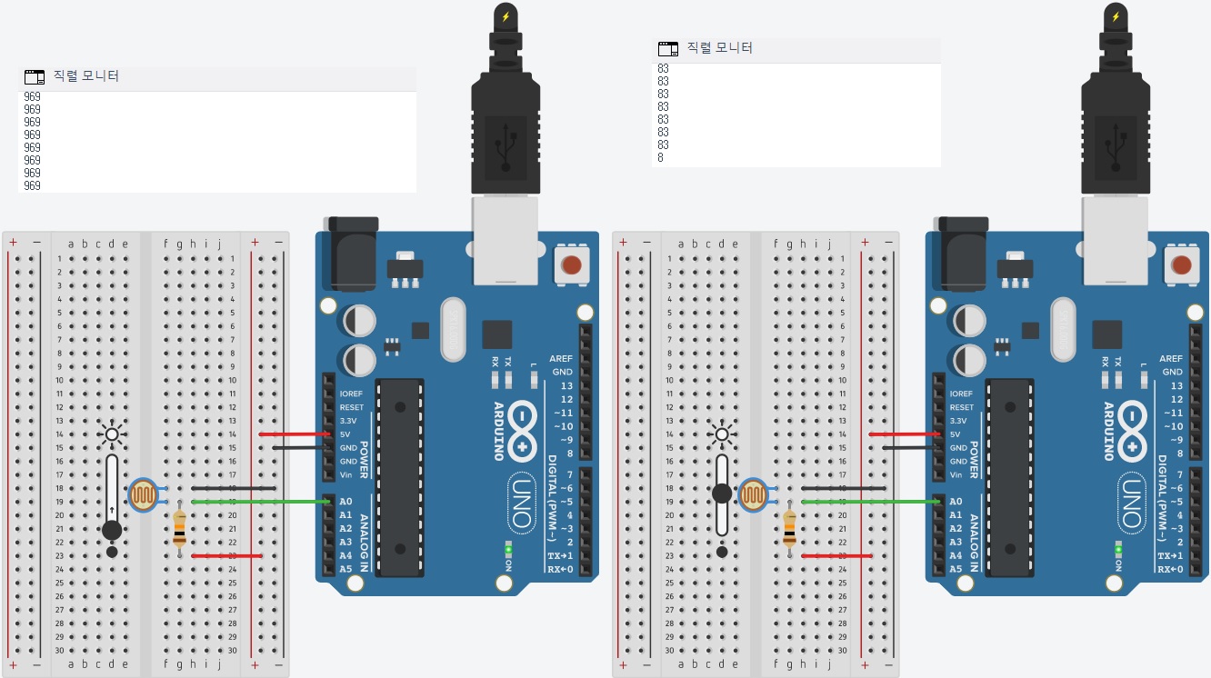
: 빛의 세기에 따라 저항값이 변하는 전자 부품,
빛이 많이 들어오면 저항이 작아지고,
적게 들어오면 저항이 커지는 황화카드뮴(CdS, cadimium sulfide)라는 화합물 사용,
극성 없음
11. 07_04 조도센서
** 저항 : 10KΩ

void setup()
{
  Serial.begin(9600);
}

void loop()
{
  int photoresistor = analogRead(A0);	// 조도센서값 측정
  Serial.println(photoresistor);
}
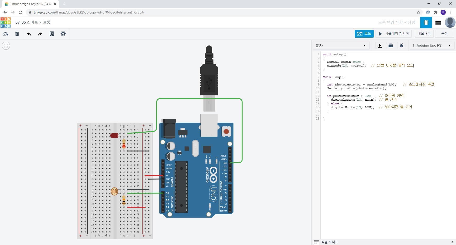
12. 07_05 스마트 가로등
** 저항 : 220Ω
** 저항 : 10KΩ

void setup()
{
  Serial.begin(9600);
  pinMode(13, OUTPUT);	// 13번 디지털 출력 모드
}

void loop()
{
  int photoresistor = analogRead(A0);	// 조도센서값 측정
  Serial.println(photoresistor);

  if(photoresistor > 100) {	// 어두워 지면
  	digitalWrite(13, HIGH);	// 불 켜기
  } else {
  	digitalWrite(13, LOW);	// 밝아지면 불 끄기
  }

}
13. 온도센서(Temperature Sensor)
: 온도에 따라 출력되는 전압이 변하는 특성을 가지는 센서로 온도가 높을수록 높은 전압을 출력으로 낸다.
세 개의 다리가 있는데 5V, GND, 가운데는 아날로그 입력핀에 연결한다.
14. 07_06 온도센서 온도계


void setup()
{
  Serial.begin(9600);	// 직렬통신 초기화
}

void loop()
{
  int input = analogRead(A0);	// 온도센서값 측정
  float voltage = input * 5.0 / 1023.0;	// 전압값 변환
  float temperature = voltage * 100 - 50;	// 온도값 변환

  Serial.print("Temperature : ");
  Serial.println(temperature);
}
15. 아날로그 입력은 가변저항, 조도센더, 온도센서 총 3개를 배웠다.
16. 원래 아두이노는 디지탈 기기이기 때문에 아날로그 신호를 그대로 처리 불가
> 따라서 아날로그에서 디지털 신호로 변환 필요하다.
** 출력값으로 아날로그 신호로 보내고 싶다면? 신호변조가 필요
[이때] PWM(Pulse Wave Modulation, 펄스 폭 변조)을 이용,
입력받은 디지털 신호를 아날로그 신호로 변환해서 출력 가능
17. 08_01 아날로그LED 밝기
** 저항 : 220Ω

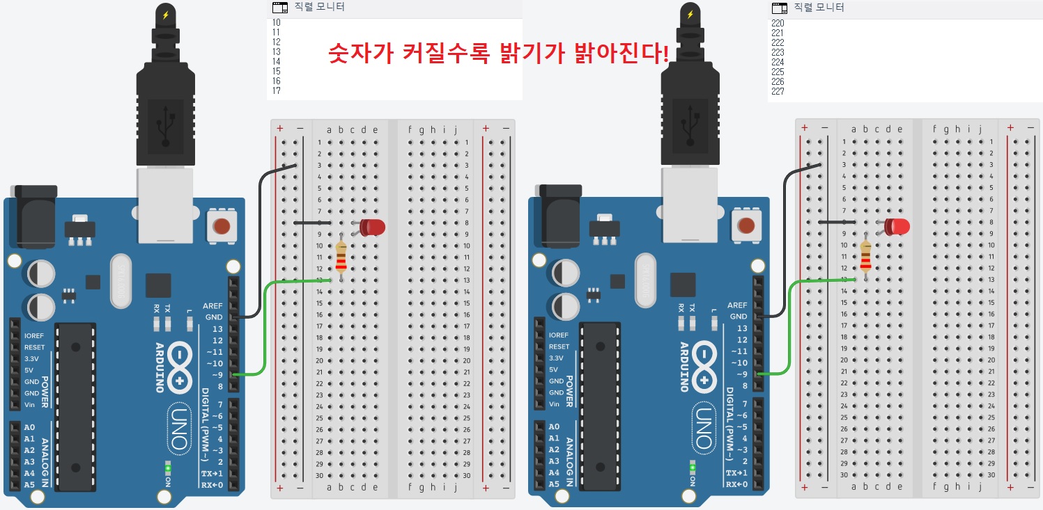
void setup()
{
  Serial.begin(9600);
  pinMode(9, OUTPUT);  // 디지털 9번 핀을 출력모드로 설정.
}

void loop()
{
  for(int i = 0; i <= 255; i++) { // 0 ~ 255
    analogWrite(9, i);	// PWM이 가능한 9번 핀에 아날로그 신호 출력
    Serial.println(i);
    delay(10);	// 10ms 지연
  }
}
18. 08_02 삼색 LED(RGB LED)
** 저항 : 220Ω
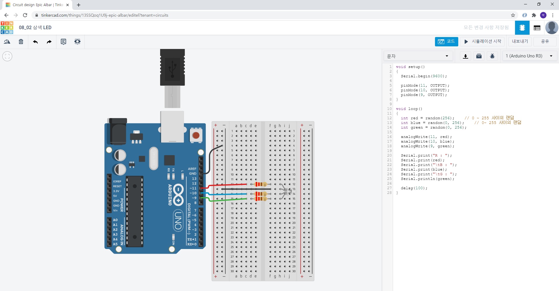

void setup()
{
  Serial.begin(9600);

  pinMode(11, OUTPUT);
  pinMode(10, OUTPUT);
  pinMode(9, OUTPUT);
}

void loop()
{
  int red = random(256);	// 0 ~ 255 사이의 랜덤
  int blue = random(0, 256);	// 0~ 255 사이의 랜덤
  int green = random(0, 256);

  analogWrite(11, red);
  analogWrite(10, blue);
  analogWrite(9, green);

  Serial.print("R : ");
  Serial.print(red);
  Serial.print("\tB : ");
  Serial.print(blue);
  Serial.print("\tG : ");
  Serial.println(green);

  delay(100);
}
19. DC모터(Direct Current Motor)
: 가변저항, 슬라이드 스위치 > DC 모터 제어
20. 08_03 DC모터제어


void setup()
{
  // PWM 지원하는 9번핀을 출력 모드로
  pinMode(9, OUTPUT);
}

void loop()
{
  int input = analogRead(A0);

  // 가변저항의 입력값(0 ~ 1023) 범위를  (0 ~ 255) 범위로 변환
  int value = map(input, 0, 1023, 0, 255);

  // 가변 저항의 값에 따라 모터의 속도 조절
  analogWrite(9, value);
}
21. 모터 단자에 연결된 선의 위치를 서로 바꾸면 모터의 회전 방향이 바뀐다.
22. 08_04 DC모터방향제어
** 저항 : 10KΩ


void setup()
{
  // PWM 지원하는 9번, 10번 핀을 출력 모드로
  pinMode(9, OUTPUT);
  pinMode(10, OUTPUT);

  // 스위치 입력 받기 위해 8번 핀 입력 모드로
  pinMode(8, INPUT);

}

void loop()
{
  int input = analogRead(A0);

  // 가변저항의 입력값(0 ~ 1023) 범위를  (0 ~ 255) 범위로 변환
  int value = map(input, 0, 1023, 0, 255);

  // 스위치 입력값에 따라 DC모터 방향 제어
  int inputSwitch = digitalRead(8);

  if(inputSwitch == LOW) {
    // Low인 경우 9번 핀에 전원 공급
    // 10번 핀은 전원 공급 안할 것임
    analogWrite(9, value);
    analogWrite(10, 0);
  } else {
  	// HIGH인 경우 10번 핀에 전원 공급
    // 9번 핀에 전원 공급 안할 것임
    analogWrite(9, 0);
    analogWrite(10, value);
  }

  // 가변 저항의 값에 따라 모터의 속도 조절
  analogWrite(9, value);

}
23. 초음파 센서(ultrasonic sensor)
: 소리, 공기의 진동에 의해 전달,
1초동안 진동한 회수 > 주파수(Hz 단위 사용),
16 ~ 20,000 Hz,
초음파 센서는 물체 사이의 거리 측정
24. 거리, 속력, 시간
1) 거리 = 속력 x 시간
2) 속력 = 거리 / 시간
3) 시간 = 거리 / 속력
25. 09_01 초음파센서 거리측정
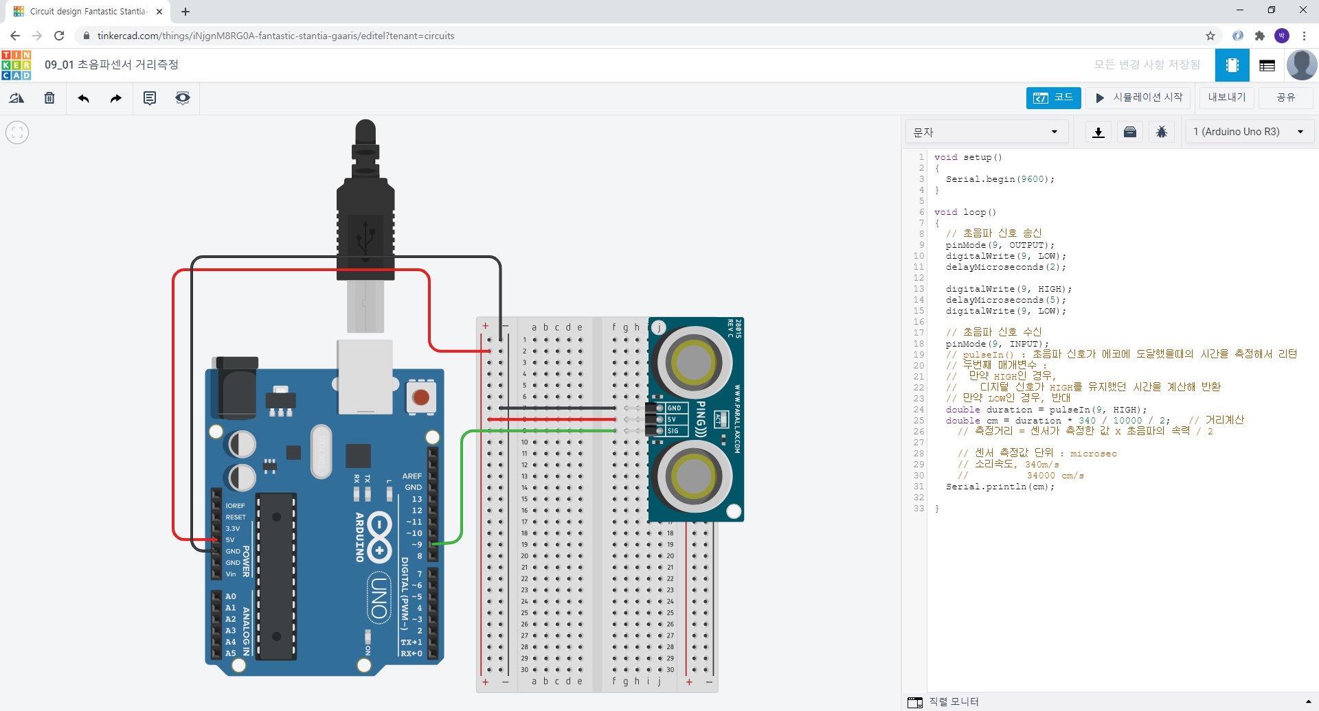

void setup()
{
  Serial.begin(9600);
}

void loop()
{
  // 초음파 신호 송신
  pinMode(9, OUTPUT);
  digitalWrite(9, LOW);
  delayMicroseconds(2);

  digitalWrite(9, HIGH);
  delayMicroseconds(5);
  digitalWrite(9, LOW);

  // 초음파 신호 수신
  pinMode(9, INPUT);
  // pulseIn() : 초음파 신호가 에코에 도달했을때의 시간을 측정해서 리턴
  // 두번째 매개변수 :
  //  만약 HIGH인 경우,
  //	디지털 신호가 HIGH를 유지했던 시간을 계산해 반환
  // 만약 LOW인 경우, 반대
  double duration = pulseIn(9, HIGH);
  double cm = duration * 340 / 10000 / 2;	// 거리계산
  	// 측정거리 = 센서가 측정한 값 X 초음파의 속력 / 2

  	// 센서 측정값 단위 : microsec
  	// 소리속도, 340m/s
  	// 			34000 cm/s
  Serial.println(cm);

}
26. 09_02 초음파 물체거리 반응LED
** 저항 : 220Ω
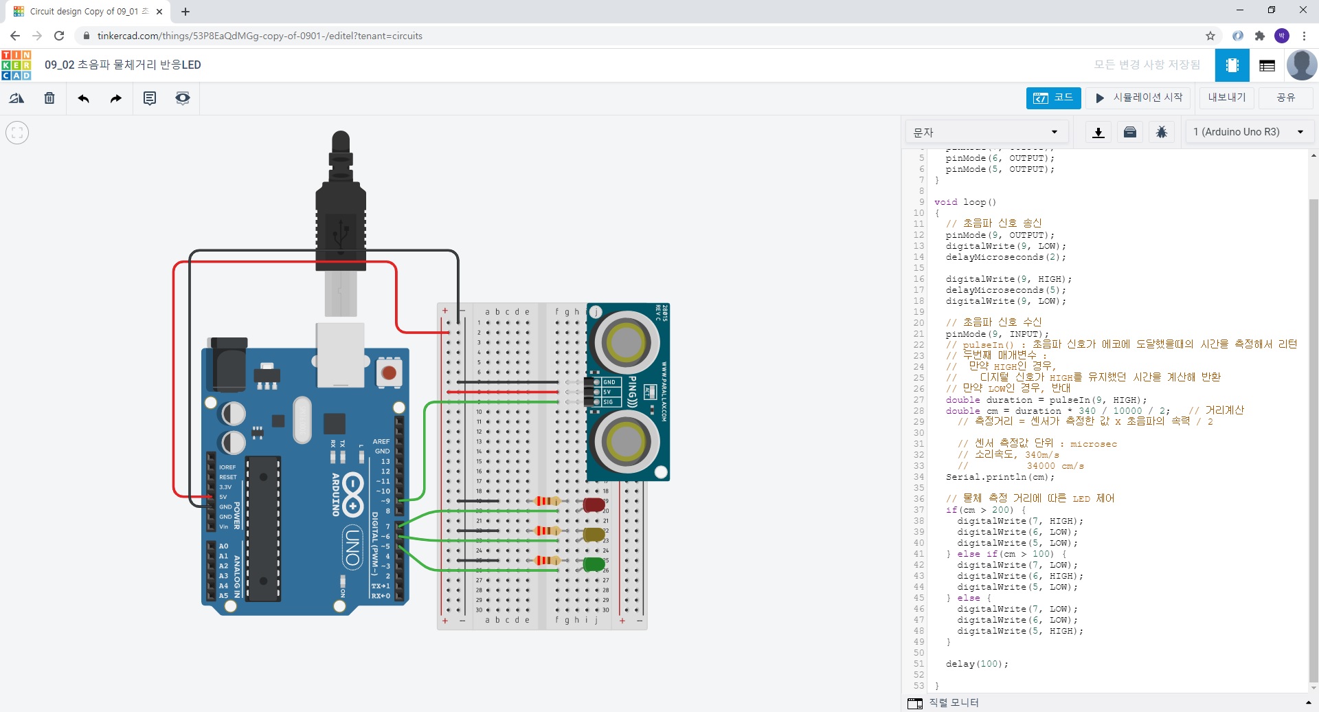

void setup()
{
  Serial.begin(9600);
  pinMode(7, OUTPUT);
  pinMode(6, OUTPUT);
  pinMode(5, OUTPUT);
}

void loop()
{
  // 초음파 신호 송신
  pinMode(9, OUTPUT);
  digitalWrite(9, LOW);
  delayMicroseconds(2);

  digitalWrite(9, HIGH);
  delayMicroseconds(5);
  digitalWrite(9, LOW);

  // 초음파 신호 수신
  pinMode(9, INPUT);
  // pulseIn() : 초음파 신호가 에코에 도달했을때의 시간을 측정해서 리턴
  // 두번째 매개변수 :
  //  만약 HIGH인 경우,
  //	디지털 신호가 HIGH를 유지했던 시간을 계산해 반환
  // 만약 LOW인 경우, 반대
  double duration = pulseIn(9, HIGH);
  double cm = duration * 340 / 10000 / 2;	// 거리계산
  	// 측정거리 = 센서가 측정한 값 X 초음파의 속력 / 2

  	// 센서 측정값 단위 : microsec
  	// 소리속도, 340m/s
  	// 			34000 cm/s
  Serial.println(cm);

  // 물체 측정 거리에 따른 LED 제어
  if(cm > 200) {
    digitalWrite(7, HIGH);
    digitalWrite(6, LOW);
    digitalWrite(5, LOW);
  } else if(cm > 100) {
    digitalWrite(7, LOW);
    digitalWrite(6, HIGH);
    digitalWrite(5, LOW);
  } else {
    digitalWrite(7, LOW);
    digitalWrite(6, LOW);
    digitalWrite(5, HIGH);
  }

  delay(100);

}'웹_프론트_백엔드 > JAVA프레임윅기반_풀스택' 카테고리의 다른 글
| 디바이스_애플리케이션_구현 시험(아두이노 프로젝트) (0) | 2020.07.14 |
|---|---|
| 2020.07.13 (0) | 2020.07.13 |
| 2020.07.09 (0) | 2020.07.09 |
| 2020.07.08 (0) | 2020.07.08 |
| 애플리케이션_테스트 시험(제출 코드와 풀이) (0) | 2020.07.07 |